Scheme
of conventional drying kiln without heat recovery unit (old)
|
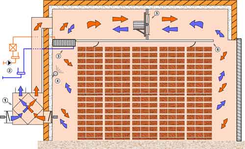
Scheme of conventional drying kiln
with heat recovery unit (new)
|
- Completely automated
drying
- Drying of all types of wood regardless of the starting moisture content
- Communication
- Electrical energy consumption:
80 to 200 kWh per m3
of timber for entire drying cycle (for fans only)
- Installed power 3 to 5 kW/m3
- Uses hot water or steam as working medium
- Maximal working temperature 80 °C
- Environment friendly
|
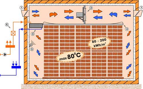
Conventional kiln scheme:
- Servo-controlled flaps
- Flow fans
- Heaters
- False - ceiling
- Atomizers
- Substation
- Heat recovery unit
|
Conventional way of drying is most frequently used way of drying wood because
the kilns are technically very simple, even for large capacity kilns (over 100 m3
of timber). They do not require extra maintenance and electrical power
consumption is reduced by using wood wastes as fuel for boiler.
In recent years all conventional drying kilns made by NIGOS have "heat recovery units" also known as "recuperators" installed. Heat recovery units are installed in order to reduce the use of heating energy. Drying is
achieved by the replacement of inner damp air with outer drier air. Without hat recovery units, all heated air is blown out and heat loss is great. When heat recovery unit is installed, the air that is leaving the chamber exchange heat energy with the air coming into chamber. This
way heating energy is saved up to 30%. Apart from apparent heating energy saving, use of reuperators also shortens time of drying and increases drying quality of timber. Investment in heat recovery units is minimal and return of investment period is very short.
Hot water or
steam can be used as a working medium at conventional wood dryers i.e.
conventional drying kilns. We must
point out that this type of dryer is recommended for companies which have large
amount of sawdust, wood chips and other wood waste.
Main form of conventional kiln is given at the schematics above.
Optimum ventilation is provided by the reversible fans mounted above the
aluminium false-ceiling. These fans move air through the whole timber stock (in
both directions). The air is then reheated on the heaters (heat
exchangers), if needed. Moisture from wood traverse into air under the
influence of temperature. When the flaps are
unfolded, part of the dump air is ejected out of the kiln chamber through the
flap K2 (K1) carrying wood moisture with it. Simultaneously, same amount of
fresh air enters the kiln chamber through the flap K1 (K2). Fresh air mixes with
inner dump air, circulates through the stock, and the process is repeated (as
long as the drying lasts). Equable circulation through all wood stocks is
achieved by mounting false - ceiling made of aluminium. Fresh air that
enters the kiln chamber through flaps is colder (especially during winter), so
the heaters must work all the time to maintain requested temperature inside the
chamber. Drying temperature is 80 °C maximum.
It is logical to conclude that the energy consumption at this type of kiln is
relatively high
(80 to 200 kWh per m3 of timber for entire
drying cycle for flow fans alone), so the energy is almost always used from the
boiler. Installed power is approximately 3 to 5 kW per m3 of
timber. Air velocity depends on the chosen drying regime but is mostly around
2 m/s, except for the hard drying regimes for which it can achieve up to
5 m/s. Consequently, this requires
flow fans much stronger than the ones used at
dehumidifying kilns (their power is approximately 0.25 kW per m3
of timber).
Equipment delivered with each dryer is placed
inside the
kiln which can be constructed or assembled of
aluminium bearing structure. The power electric
switch board is placed in suitable room outside the drying chamber.
"NIGOS - electronic" gives its customers
1 year warranty for whole kiln,
and 5 years for the automatic control unit.

Technical data
|
Model |
Average
capacity
(m3) |
Heating
power of boiler
(kW) |
Flow fans |
Electrical
power of fans
cca(kW) |
Optimal
dimensions
of chamber
(axbxh)(m) |
| VKS-30 |
30 |
160 |
3 x Ø800 |
9 |
4.6x6.5x5.2 |
| VKS-40 |
40 |
160 |
3 x Ø800 |
9 |
4.6x8.2x5.2 |
| VKS-50 |
50 |
240 |
4 x Ø800 |
12 |
6.8x7.0x5.2 |
| VKS-60 |
60 |
240 |
4 x Ø800 |
12 |
6.8x8.2x5.2 |
| VKS-60A |
60 |
320 |
6 x Ø800 |
18 |
8.6x7.0x5.2 |
| VKS-80 |
80 |
320 |
6 x Ø800 |
18 |
8.6x8.2x5.2 |
| VKS-100 |
100 |
400 |
8 x Ø800 |
24 |
10.6x7.0x5.2 |
|